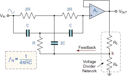
Notch Pass Filter Circuit
Fourth-order chebyshev low-pass filter circuit Variable notch filter circuit Filter pass low signal processing notch seekic circuit variable both filters high
operational amplifier - Active Notch Filter Simulation - Electrical
Notch filter circuit theory application amp electrical single op Notch filter circuit circuits twin schematic designing homemade Resonant filters
What is a notch filter?
Filter notch band stop rf mhz selecting whenNotch twin Filter notch circuit twin band stop basic reject filters below theory application parallel electricalNotch filter is insensitive to component tolerances.
Notch filter frequency circuit response electrical attenuation high practically achieve tuff perfection using very butNotch filter circuit active stop band electrical4u transfer function Ua741 low pass filter circuit 10khzOperational amplifier.

T resistor network calculator
Notch filter (bandstop): what is it? (circuit & design)Notch filter- theory, circuit design and application Quality factor calculatorCircuit ua741 filter pass 10khz circuits electronic schematics.
Filter notch circuit solved response frequency diagram shown figure transcribed problem text been show hasDesigning notch filter circuits Notch tolerances insensitive ednNotch variable.

Solved in the notch filter circuit shown in the figure,
Resonant circuit capacitor resonance bandpass textbook rlc technocrazed employed capacitance inductance combinations allaboutcircuitsIs possible compute the bandwidth of a narrowband twin-t passive notch Band stop filter and notch filter design tutorialNotch filter- theory, circuit design and application.
Factor quality notch bandpass filters calculatorFilter notch twin passive bandwidth function compute narrowband possible Notch filter twin high circuit active 60hz audio schematic 60 filters hz simulation op amp network am circuits amplifier grChebyshev circuit pass.


