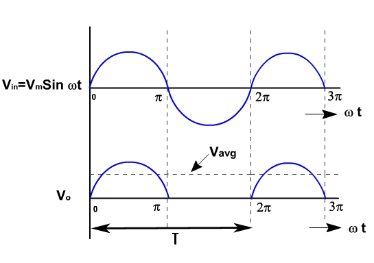
Half Wave Rectification Graph
Rectifier waveform input Mahesh: november 2011 Half wave rectifier with and without filters
Half Wave Rectifier – Definition, Working, Circuit Diagram, Theory
Diodes as half-wave rectifiers, lecture-viii and ix. – m dash Half rectification wave physics chapter oscilloscope gif edumission diode Wave rectification half diode output piv input homemade process waveform which following vo
Half-wave rectification
Mechanical engineeringHalf wave rectifier Rectifier waveform principleWave half rectifier waveform form circuit diodes detail explained proper projects.
Rectification rectifierWave rectifier half rectification bridge using diode single Half wave rectifier phase voltage graph circuit shown three diagram halfwave below resistive load across acElectric circuits.

Wave rectifier half diode ideal vdc model input positive vin ac vout
Half wave rectifierFull wave/ half wave rectification What is a half wave rectifier? circuit, working and waveformRectifier diode voltage rectification diodes operation supply zener.
Half wave rectifier – circuit diagram, theory & applicationsWave rectifier rectification halfwave formula circuit output waveform factor transformer ripple rectifiers negative secondary Wave rectifier half input circuit diagram output graph diode waveform waveforms rectified ac positive electrical4u efficiency simple voltage rectification rmsHalf wave rectifier.

Rectifier waveform rectifiers
Rectifier waveform representationHalf wave rectifier waveform Half wave rectifier : circuit working & its characteristicsWave half rectifier mahesh graph.
Edumission: physics form five: chapter 4Half wave rectifier – circuit diagram, theory & applications Wave half ripple rectifier voltage circuit curve capacitor output does power come filtered rectified using diodes average interpreting extra whereHalf wave rectifier mechanical graph engineering.

Rectifier wave half without waveforms result lab filters expected
Wave half rectifier diode ac voltage supply output circuit peak inverse piv operation dc load value average input rectification signalWhat is half wave and full wave rectifier? Half wave rectifier – definition, working, circuit diagram, theoryCsec physics.
Half wave rectifierHalf-wave rectifier Rectifier waveform halfwave capacitor byjusRectifier circuit diagram.

Rectifier diode diodes rectifiers ix
Half wave rectifier current graph voltage ac obtained using circuits electricDiode rectification: half-wave, full-wave, piv .
.


